KEYPAD INTERFACING WITH ARDUINO
Whenever a key is pressed in keypad module the Arduino detects it and shows the corresponding key on 16×2 LCD. In this tutorial we are going to interface 4×4 keypad with Arduino.
Synopsis

In embedded devices one of the essential parts is keypad and it is used to interact with embedded devices. Keypad is input device which is used to give commands to other devices. From calculator to computer input is given through keypad. In this tutorial we are going to interface 4×4 keypad with Arduino. Here also we are using ATmega328p microcontroller instead of Arduino.

Whenever a key is pressed in keypad module the Arduino detects it and shows the corresponding key on 16×2 LCD. The 16x2 is very common type LCD, with two rows, and each row displays 16 characters.

Description

Hex key pad is simply an arrangement 0f 16 push button switches in a 4X4 matrix form. Typically a hex keypad will have keys for number 0, 1, 2, 3, 4, 5, 6, 7, 8, 9 and letters A, B, C, D, *, #. The hex keypad will have 8 connection wires namely R1, R2, R3, R4 and C1, C2, C3, C4 representing the rows and columns respectively. The schematic diagram and photo of a typical hex keypad is shown in the figure below.


The program identifies the pressed key by a method called column scanning. In this method a particular row is kept low and other rows are held high. Then the logic status of each column line is scanned. If a particular column is found low, which means the key comes in between that column and row is short (pressed). Then the program registers that key being pressed. The same procedure is applied for the subsequent rows and the entire process is repeated. For example if row 1 is kept low and column 1 is found low during scanning that means key “1” is pressed.

LCD can be used either in 4-bit mode or 8-bit mode. In 4-bit mode it requires 7 IO pins of the Arduino. In 8 bit mode 11 IO pins required from Arduino.

Arduino IDE has a library which contains important functions to get this module up and running. I wanted to build a library for Atmega328p which does almost similar functions as Keypad Library in Arduino IDE.

ATmega 328p

The Atmel 8-bit AVR RISC-based microcontroller combines 32KB ISP flash memory with read-while-write capabilities, 1KB EEPROM, 2KB SRAM, 23 general purpose I/O lines, 32 general purpose working registers, three flexible timer/counters with compare modes, internal and external interrupts, serial programmable USART, a byte-oriented 2-wire serial interface, SPI serial port, 6-channel 10-bit A/D converter (8-channels in TQFP and QFN/MLF packages), programmable watchdog timer with internal oscillator, and five software selectable power saving modes. The device operates between 1.8 to 5.5 volts. The device achieves throughout approaching 1 MIPS per MHz.

VCC: Digital supply voltage.

RESET: If the RSTDISBL fuse is programmed, PC6 is used as an input pin. If the RSTDISBL fuse is not programmed, PC6 is used as a reset input. A low level on this pin for longer than the minimum pulse length will generate a reset.

AVCC is the supply voltage pin for the A/D converter. It should be externally connected to VCC, even if the ADC is not used. If the ADC is used, it should be connected to VCC through a low-pass filter.

Port B (PB7:0) XTAL1/XTAL2/TOSC1/TOSC2 is an 8-bit bi-directional I/O port with internal pull-up resistors (selected for each bit). The Port B output buffers have symmetrical drive characteristics with both high sink and source capability.

Port D is an 8-bit bi-directional I/O port with internal pull-up resistors (selected for each bit). The port D output buffers have symmetrical drive characteristics with both high sink and source capability. As inputs, port D pins that are externally pulled low will source current if the pull-up resistors are activated. The port D pins are tri-stated when a reset condition becomes active, even if the clock is not running.

Depending on the clock selection fuse settings, PB6 can be used as input to the inverting oscillator amplifier and input to the internal clock operating circuit.

Depending on the clock selection fuse settings, PB7 can be used as output from the inverting oscillator amplifier.

Proteus design for Keypad interfacing with Arduino


Orcad design for Keypad interfacing with Arduino


Keypad interfacing with Arduino

/*  Name     : main.c
 *  Purpose  : Source code for Keypad Interfacing with Arduino.
 *  Author   : Gemicates
 *  Date     : 18-01-2018
 *  Website  : www.gemicates.org
 *  Revision : None
 */
#include<LiquidCrystal.h>                   // this header file has instructions written in it, which enables
                                            // the user to interface an LCD to UNO in 4 bit mode without any fuzz

LiquidCrystal lcd(8, 9, 10, 11, 12, 13);    // sets the interfacing pins
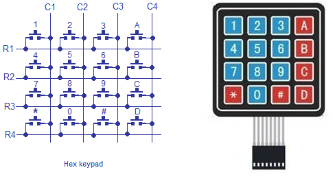
int R1=0;                                   // declares R1, R2, R3, R4, C1, C2, C3, C4,
int R2=1;                                   // D4, D5, D6, D7 as integer type
int R3=2;
int R4=3;
int C1=4;
int C2=5;
int C3=6;
int C4=7;
int D4;
int D5;
int D6;
int D7;

void setup()
{
    pinMode(R1,OUTPUT);                     // initialize the digital pins R1, R2, R3, R4 as outputs
    pinMode(R2,OUTPUT);
    pinMode(R3,OUTPUT);
    pinMode(R4,OUTPUT);
    pinMode(C1,INPUT);                      // initialize the digital pins C1, C2, C3, C4 as inputs
    pinMode(C2,INPUT);
    pinMode(C3,INPUT);
    pinMode(C4,INPUT);
    digitalWrite(C1,HIGH);                  // Drive C1, C2, C3, C4 to HIGH
    digitalWrite(C2,HIGH);
    digitalWrite(C3,HIGH);
    digitalWrite(C4,HIGH);
    lcd.begin(16, 2);                       // initializes the 16*2 LCD
    lcd.setCursor(0,0);                     // sets the cursor at row 0 column 0
    lcd.print("16*2 LCD MODULE");           // prints 16*2 LCD MODULE
 }

void loop()
{
    lcd.setCursor(0,1);                     // sets the cursor at row 0 column 1
    digitalWrite(R1,LOW);                   // Drive R1 to LOW
    digitalWrite(R2,HIGH);                  // Drive R2, R3 ,R4 to HIGH
    digitalWrite(R3,HIGH);
    digitalWrite(R4,HIGH);
    D4=digitalRead(C1);                     // sets D4 equal to the input C1
    D5=digitalRead(C2);                     // sets D5 equal to the input C2
    D6=digitalRead(C3);                     // sets D6 equal to the input C3
    D7=digitalRead(C4);                     // sets D7 equal to the input C4
    
    if(D4==LOW)
    {
      lcd.print("7");                       // prints '7'
    }
    
   else
    {
      if(D5==LOW)
      {
        lcd.print("8");                     // prints '8'
      }
  
   else
   {
    if(D6==LOW)
    {
      lcd.print("9");                       // prints '9'
    }
  
   else
   {
   if(D7==LOW)
   {
    lcd.print("/");                         // prints '/'
   }
   }}}

   digitalWrite(R1,HIGH);                   // Drive R1 to HIGH
   digitalWrite(R2,LOW);                    // Drive R2 to LOW
   digitalWrite(R3,HIGH);                   // Drive R3, R4 to HIGH
   digitalWrite(R4,HIGH);
   D4=digitalRead(C1);                      // sets D4 equal to the input C1
   D5=digitalRead(C2);                      // sets D5 equal to the input C2
   D6=digitalRead(C3);                      // sets D6 equal to the input C3
   D7=digitalRead(C4);                      // sets D7 equal to the input C4
   
   if(D4==LOW)
   {
    lcd.print("4");                         // prints '4'
   }
  
   else
   {
    if(D5==LOW)
    {
      lcd.print("5");                       // prints '5'
    }
   
  else
  {
    if(D6==LOW)
    {
      lcd.print("6");                       // prints '6'
    }
    
  else 
  {
    if(D7==LOW)
    {
      lcd.print("X");                       // prints 'X'
    }
    
   }}}

  digitalWrite(R1,HIGH);                    // Drive R1, R2 to HIGH
  digitalWrite(R2,HIGH);
  digitalWrite(R3,LOW);                     // Drive R3 to LOW
  digitalWrite(R4,HIGH);                    // Drive R4 to HIGH
  D4=digitalRead(C1);                       // sets D4 equal to the input C1
  D5=digitalRead(C2);                       // sets D5 equal to the input C2
  D6=digitalRead(C3);                       // sets D6 equal to the input C3
  D7=digitalRead(C4);                       // sets D7 equal to the input C4
  
  if(D4==LOW)
  {
    lcd.print("1");                         // prints '1'
  }
 
  else
  {
    if(D5==LOW)
    {
      lcd.print("2");                       // prints '2'
    }
   
  else 
  {
    if(D6==LOW)
    {
      lcd.print("3");                       // prints '3'
    }
   
  else 
  { 
    if(D7==LOW)
    {
      lcd.print("-");                       // prints '-'
    }
   }}}
   
  digitalWrite(R1,HIGH);                    // Drive R1, R2, R3 to HIGH
  digitalWrite(R2,HIGH);
  digitalWrite(R3,HIGH);
  digitalWrite(R4,LOW);                     // Drive R4 to LOW
  D4=digitalRead(C1);                       // sets D4 equal to the input C1
  D5=digitalRead(C2);                       // sets D5 equal to the input C2
  D6=digitalRead(C3);                       // sets D6 equal to the input C3
  D7=digitalRead(C4);                       // sets D7 equal to the input C4
  
  if(D4==LOW)
  {
    lcd.print(" ");                         // prints nothing
  }
  
  else
  {
    if(D5==LOW)
    {
      lcd.print("0");                       // prints '0'
    }
    
   else
   {
    if(D6==LOW)
    {
      lcd.print("=");                       // prints '='
    }
    
   else
   {
    if(D7==LOW)
    {
      lcd.print("+");                       // prints '+' 
    }
    
   }}}
   
}  

Error message here!

Show Error message here!


Forgot your password?

Error message here!

Send OTP

Error message here!

Show Error message here!


Lost your password? Please enter your email address. You will receive a password you Need.

Send Error message here!


Back to log-in

Close